Automated Deburring & Surface Finishing

Keith Brown • September 5, 2025

Engineered Surface Solutions (E.S.S.)

Who We Are

E.S.S. specializes in mechanical and chemical surface enhancements. Our mission is simple: faster burr removal, better finishes, less hassle.


What’s New

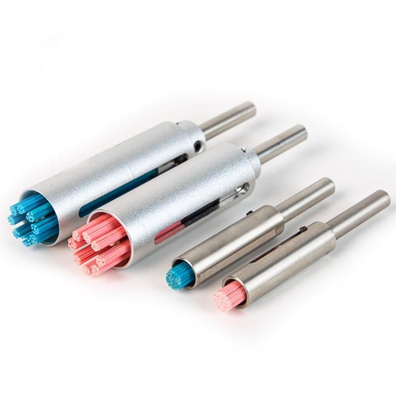
We proudly introduce our automated deburring and surface finishing solutions powered by proprietary ceramic extruded fibers. Our unique fiber geometry delivers unmatched grinding power with the mechanical capability to remove burrs up to 0.010" in root thickness while upgrading surface finish.


Where It Shines

·         Inconel®, Hastelloy®, Monel®, Stellite®, René alloys, Titanium

·         300 & 400 Series Stainless Steels

·         Hardened steels up to 70 HRC


Cross-Hole Breakthrough

Our cross-hole brushes eliminate the need for “lollipops” whenever the backside of the cross-hole is accessible from the main bore. Thanks to our fiber design and long-range force distribution, E.S.S. brushes out-flex conventional media while maintaining cutting pressure deep into features.


Performance + Value

·         Typical pricing delivers 20–25% savings vs. incumbent solutions.

·         Further gains from time saved, longer tool life, higher throughput, and expert application support.


Call to Action

If your deburring results—or your vendor support—have gone dull, step up to E.S.S. You won’t be disappointed.


Contact us for more information


By Keith Brown August 21, 2026
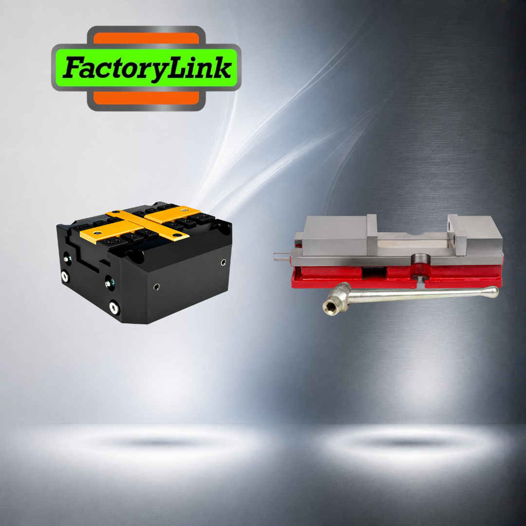
A vise that's wrong for the job doesn't announce itself. It shows up as a cycle-time bottleneck nobody can quite explain, a thin-wall part that scrapped for no obvious reason, or an operator fighting a setup that should take seconds. And here's what makes it easy to miss: the vise causing it is usually a perfectly good vise — just not for that work. Walk any shop floor and you'll find both kinds running side by side: the mechanical vise cranked by hand for decades, and the pneumatic vise clamping and releasing in under a second while nobody touches it. Both are good. That doesn't mean both are good for you. They solve different problems, and the wrong one on your table costs you either cycle time or capability. The question was never which vise is "better" — it's which one your work is actually asking for. Here's how to tell. How They Differ A mechanical vise clamps by hand — a lead screw and handle drive the jaws, and the operator feels the part come tight. A pneumatic vise clamps with compressed air: hit the switch and the jaws close with the same force every cycle, no crank required. That single difference — muscle versus air — drives every tradeoff that follows. Where the Pneumatic Vise Wins Speed is the headline. A pneumatic vise clamps and releases in under a second, which adds up fast across a long run. It delivers identical clamping force on every cycle automatically, so part number one and part number five hundred see the same pressure — a real advantage on thin-wall or fragile parts where too much force crushes and too little lets the part move. It takes the operator's hands out of the loop, cutting fatigue on repetitive loading. And it's automation-ready: tie it to your CNC controls or a robotic loader and the machine runs unattended. The cost of all that: you need plumbed shop air at the machine, and the vise gives up some of the raw holding power a hand-cranked or hydraulic unit can generate. Reach for pneumatic when: you're running high volume and every second of load time matters; you're holding delicate parts that demand repeatable, controlled pressure; or you're building an automated or lights-out cell where a robot loads the work. Where the Mechanical Vise Wins Holding power and control. A mechanical vise generates massive clamping pressure for heavy cutting, and it gives the operator tactile feedback — you feel exactly how tight the part is, which matters on a one-off or an odd setup. It costs less up front, needs no air lines, and moves from machine to machine without disconnecting any utilities. For a shop that changes part sizes constantly, quick manual adjustment beats reconfiguring an automated clamp. Reach for mechanical when: you're doing heavy milling and need maximum rigidity; you run high-mix, low-volume work where setups change all day; or you're in the toolroom on prototypes, where setup speed matters more than cycle speed. The Quick Decision If your bottleneck is cycle time and repetition, go pneumatic. If your bottleneck is holding force, flexibility, or setup speed on varied work, go mechanical. High-volume automated production leans air; high-mix toolroom and heavy roughing lean iron. Where 5th Axis Fits — Both Sides of the Table Here's what makes this an easy conversation: at FactoryLink Inc., we support precision workholding from 5th Axis — and 5th Axis builds for both sides of it. Need to hold hard on heavy stock, or change setups all day in the toolroom? Their mechanical self-centering vises close dead on center on a left- and right-handed leadscrew, and they're RockLock™-ready, so a manual vise today can drop into an automated setup tomorrow. Running a robot cell or thousands of parts a shift? Their APV Series pneumatic clamping vises deliver the same force every cycle, triggered by M-code, PLC, or robot — with two force tiers to match the work: the APV-160-A for high-force holding and the APV-160-B for a longer, more forgiving stroke on everyday production. So whether your next job calls for the grip of iron or the speed of air, you're not choosing between brands — you're choosing the right tool from one you already trust. The chart below breaks down which type fits which work. Not sure which way your application leans? Reach out to FactoryLink Inc. Tell us the part size, cycle time, and air supply, and we'll help you land on the right workholding.
By Keith Brown August 14, 2026
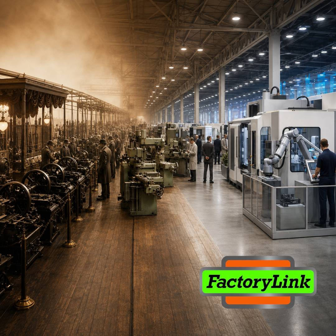
Every trade has a place where it goes to see itself clearly. For manufacturing technology, that place has a name and a schedule: the International Manufacturing Technology Show, back at McCormick Place this September for the first time since 2024. Walk the floor and it feels like the future arrived early. But the show is older than almost everyone standing in it — and its story is really the story of the trade itself. It started as a place to show what the work could do In September 1927, the first National Machine Tool Builders' Exposition opened in the Cleveland Auditorium. It filled 63,000 square feet and drew more than 12,000 people to see 428 operating machines — everything from milling machines weighing 100,000 pounds down to portable electric drills. The floor demanded more electrical power than any single-industry exposition had ever needed; organizers built a dedicated transformer station rated for 5,000 horsepower just to keep the machines running. Here's the part worth sitting with: the machines weren't for sale. The first show wasn't a marketplace. It was closer to a science fair — a place for the trade to put its capability on the table and let the industry see what was possible. That instinct, showing the work rather than just pitching it, is still the best reason to walk the floor today. It survived the years that should have ended it The show has always been a mirror of the wider economy, which means it has lived through the economy's worst stretches. The 1935 exhibition arrived only after the Great Depression forced two postponements. It went on anyway, and the organizers took visible pride in persevering through a time of doubt. After that, the Second World War shut the show down entirely — no exhibitions for over a decade. When it came back in 1947, it came back big. The first postwar show leased 500,000 square feet inside the old Dodge plant on South Cicero Avenue in Chicago — the building Tucker was taking over — and it turned loose a wave of manufacturing capability that the war years had built up behind closed doors. A show that had been dark for twelve years reopened as the launch pad for the postwar industrial boom. It's where the trade met the machine that changed everything Numerical control didn't arrive with fanfare. A few numerically controlled machines quietly caught visitors' attention at the 1955 show. But by 1960, NC wasn't a curiosity anymore — it was the center of gravity. Observers at the time openly called it 'the numerical-control show.' The idea was radical and simple at once: take the principle of the electronic computer, code instructions as numbers on punched or magnetic tape, and let servo-mechanisms move the machine. This is the ancestor of every CNC control on your floor right now. It's tempting to call 1960 the death of manual machining. It wasn't. It was the beginning of a partnership — the operator's judgment paired with the machine's repeatability — that still defines precision work today. The machine didn't replace the machinist. It gave the machinist a new instrument to be good with. It's where the trade tests ideas — including the ones that don't survive Not every breakthrough on the floor becomes the future. In 1994, Giddings & Lewis unveiled the Variax, a six-legged hexapod mill that reimagined machine geometry from the ground up. It was one of the most talked-about exhibits in the show's history — fast, precise enough to double as a coordinate measuring machine, genuinely ahead of its time. And it didn't catch on. It was expensive and complicated, and the industry moved on. A trade needs a place to try the audacious idea in public, and to decide together what's worth keeping. The Variax is remembered because the floor is where the industry does its thinking out loud. It's where a car drove off the floor that was never assembled from parts In 2014, Local Motors, Cincinnati Incorporated, and Oak Ridge National Laboratory printed a functional electric car — the Strati — live on the show floor. The carbon-fiber-reinforced body came off a Big Area Additive Manufacturing machine in about 44 hours, got finished on a CNC router, was assembled in two days, and drove off the Emerging Technology stand before the show closed, to a cheering crowd. AMT described it as returning the show to its roots as the place where the newest technology is seen first. Notice what that build actually was: additive and subtractive working together. The 3D printer made the shape; the CNC router made it right. The newest tool on the floor didn't retire the older one. It partnered with it. That's the whole story of this trade, compressed into one 44-hour build. Which brings us to this September From a 1927 science fair in Cleveland to a car printed live in Chicago, the through-line never changed: the machine never ran itself. Every milestone on that floor was a new instrument in capable hands. That's the trade we work in, and that's why we show up. Next month, FactoryLink joins that lineage as joining that lineage as proud representatives of the many brands we represent. Many of the principals we represent will be on the floor with us — the same builders, tooling makers, and technology partners whose work we put in front of shops every day. If you're planning your walk through McCormick Place September 14–19, put us on the list. We'd rather show you what the work can do than tell you about it. That's been the point since 1927.
By Keith Brown August 7, 2026
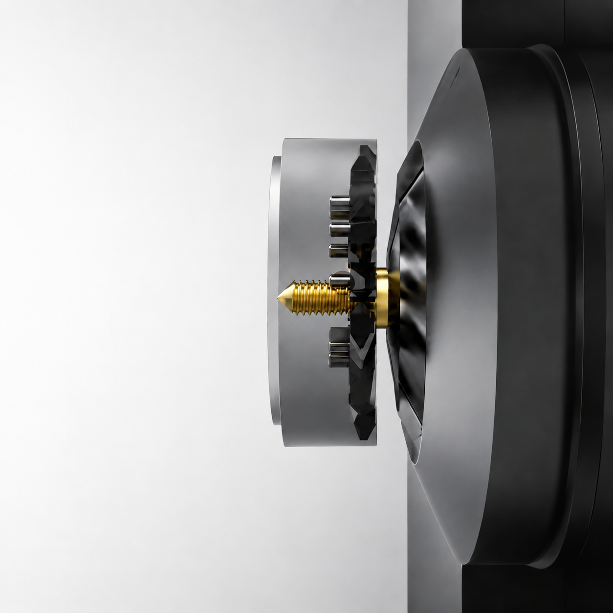
Ask anyone who runs bone screws, dental implants, or long aerospace fasteners on a Swiss machine what keeps them up at night, and thread quality on small-diameter parts is near the top of the list. The longer and thinner the part, the harder it fights back. THE PROBLEM Single-point threading works away from the part’s support. On a long length-to-diameter part — think a titanium bone screw many times longer than it is wide — the cutting force pushes against material that has room to flex. The bar deflects, and that deflection shows up as taper down the length, inconsistent thread form, and surface finish that breaks down toward the unsupported end. Because single-point threading builds the thread over multiple passes, every pass is another chance for variation to creep in, and every pass adds cycle time. In medical and aerospace work, where the thread form is often deep, increased-pitch, or multi-start, that’s not a cosmetic issue — it’s a scrap-rate issue. THE FIXES — WHAT YOU CAN TRY FIRST Before changing your whole approach, there’s real ground to gain by tightening up the process you already run. These fixes cost time and attention rather than capital: Workholding and support. Keep material support as close to the cut as possible — extended-nose guide bushings hold the bar within millimeters of the cutting point. Re-check and tighten rotary or sliding guide bushing clearance; loose clearance lets the bar push away under radial threading loads. And where the geometry allows, pre-turn the major diameter close to tolerance in a supported pass before the thread tool engages. Tooling. Move to sharp, polished, positive-geometry ground inserts rather than molded or dulled edges — a keener edge cuts cleaner and pushes less. Tough PVD-coated micro-grain carbide grades hold up to the low-to-medium surface speeds these materials demand without chipping. And an angled flank infeed, rather than a straight radial plunge, loads the cut primarily on one edge and reduces the side-pressure driving deflection. Programming. If your control supports it, apply spindle speed variation — modulating RPM by 10–20% during the cut breaks up the regenerative chatter frequency before it builds. Where the setup allows, a reverse pull-turning configuration converts radial push forces into axial tension, which stabilizes a small-diameter profile instead of bowing it. THE CEILING Here’s the honest part: these fixes help, but they manage the symptom rather than remove the cause. On a genuinely long, small-diameter threaded part, single-point threading is still working away from support and still building the form over multiple passes. There’s a point where you’ve dialed in everything you can and the process itself is the limit. THE FIX: GENSWISS® THREAD WHIRLING That’s where thread whirling changes the equation entirely. At FactoryLink Inc., we support thread whirling solutions from GenSwiss®. Instead of cutting away from support, a whirling system uses a rotating ring of inserts working right at the guide bushing — where the part is fully supported — and cuts the thread in a single pass from stock diameter. The deflection problem largely disappears because the cutting happens where the part is held, not out at the unsupported end. The advantages compound from there. Because whirling inserts get their side clearance from the tilt of the whirling spindle rather than from relieving material under the edge, they carry a stronger cutting edge and longer tool life than single-point tools. The single-pass approach eliminates the rough-and-finish insert matching that single-point threading requires, cutting setup and debugging time along with special support devices. And the finish itself is better: because the cutter enters and exits in a radial arc and contacts the part only at full tangency, whirling leaves a uniform surface — a real advantage on the 0° thread walls common on the trailing side of bone screws. GenSwiss builds this on a partnership with Utilis AG of Switzerland, putting more cutting teeth in the cut — up to twelve inserts, versus the three- and six-insert systems that came before — so a shop can run higher speeds and feeds while holding thread form. Their cutter rings, like the nine-pocket rings running double-lead custom-form inserts, are built around the exact demands of medical and aerospace threading. And where many whirling attachments run out of adjustment on multi-start threads, GenSwiss attachments adjust to ±25° of helix angle — enough range to handle the double- and triple-start threads that show up on modern implants and screws. THE PINNACLE: GENSWISS® TRUFORM® INSERTS If thread whirling is the fix, TruForm® is where it reaches its peak. GenSwiss® TruForm® triple-edge inserts are built for maximum precision in thread whirling — three cutting edges per insert, custom-ground to fit the most common three-sided whirling holders across whirling attachments and Swiss-CNC machines. Their sharper lead angles, matched to GenSwiss’s high-precision grind standards, produce burr-free threads, extended tool life, and a surface finish GenSwiss fairly calls jewelry-like. ThermoGuard and Aegis coatings keep the inserts running longer and support the high metal-removal rates that aggressive custom thread forms demand — the exact conditions found in bone screws, dental implants, worm gears, and semiconductor parts. For long, small-diameter threaded parts, that’s the full picture: cut at the guide bushing where the part is supported, put more teeth in the cut, match the helix to the thread, and finish it with an insert engineered for the peak of the process. That’s how a deflection fight becomes a repeatable, high-yield operation. Looking at a threaded part that won’t hold form on your Swiss machine? Reach out to FactoryLink Inc. to talk through whether GenSwiss® thread whirling with TruForm® inserts is the right fix for your application. For more information about how The Factory Link can improve your thread whirling workflow contact us!